When I first assembled my 5-band spiderbeam antenna, I made some mistakes. Hopefully these tips will help others who decide to assemble their own Spiderbeam.
After assembly, the main issue I hit was high SWRs. Here’s how I addressed it with the help of Rick Westerman, DJ0IP, the spiderbeam guru.
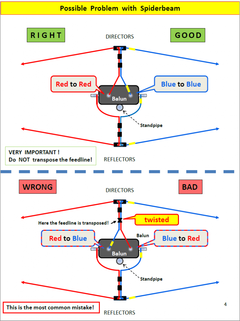
At least on my pre-assembled Spiderbeam, there are no red or blue wires as shown below (colors are for illustrative purposes only). Had the wires actually been colored, it would’ve been much more obvious what I needed to do… It’s important to understand and observe how the active Director elements are polarized and aligned, as shown below.

Be very careful that you have all the active elements and their feed lines correctly aligned, on the same side and not twisted. This aligns all of the RF that’s flowing on all wires simultaneously. As shown above, this is the most common mistake (and I made it, too).
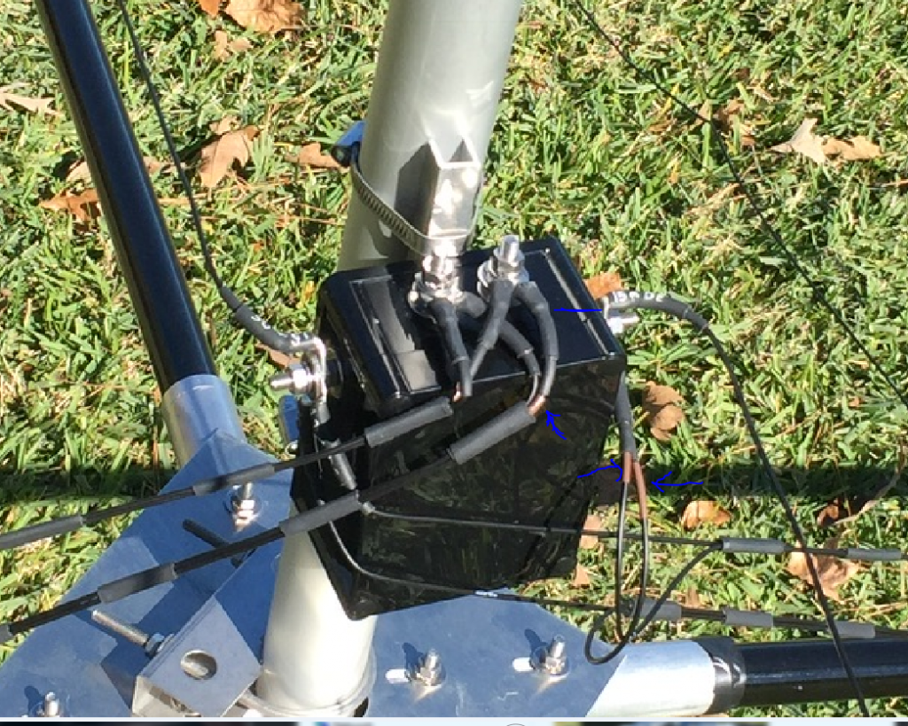
There are some little brown shrink-wrap sections on one side of each active Director element that must all be on the same side (represented in the above diagram by the little yellow rectangles). You must have the “polarity” the same on all directory elements; e.g., inner part of coax feed going to one side of the antenna, shield side feeding the opposite side (after passing through the balun). If your antenna was preassembled, then you will have the little brown shrink wraps (if you’re building your own from the kit, your milage may vary). You can see the small brown shrink wraps in this close-up below.

Fail to properly get the Director elements’ polarities correct and you will experience high SWR’s on some or all of the bands.
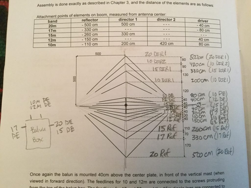
The other area of difficult with assembly was figuring out the exact spacing and ordering of all the elements. Here’s how I figured it out. Note that all centimeter distances are as measured from the stand pipe centerpoint (not where the pole starts).

I hope those assembly tips are helpful.
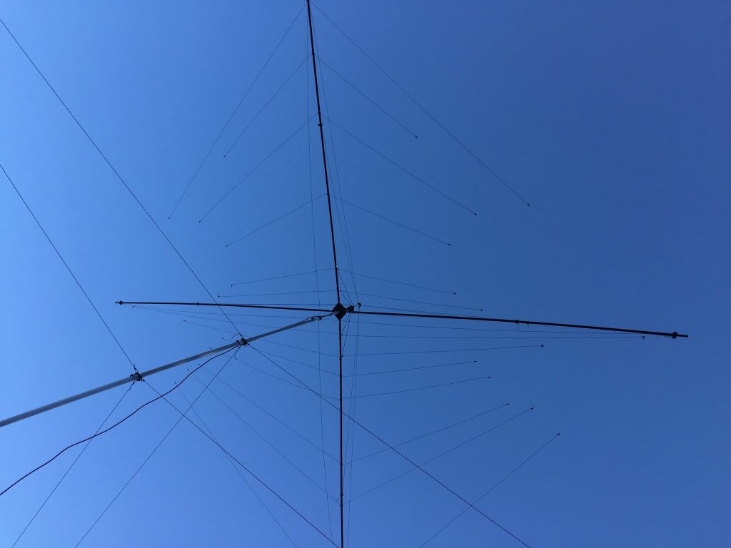
Here’s how mine looks now from underside:


Recent Comments