In this blog post, I will cover the basic process used to mount the Spiderbeam antenna onto the mast (by myself) and to raise the antenna with no assistance, other than my Easy Mast device. I like to name things to make it easy to reference them, so I’m calling it “Easy Mast” for convenience of reference only.
Using a mast for an antenna is much less expensive than installing a tower, but isn’t as easy as it sounds like it would be. For us first-time mast users, it’s even more challenging because there are certain pitfalls that aren’t properly documented by the mast providers. I will cover those as well. Among the challenges I have encountered are:
- It takes a team of at least 2 or more people to mount the antenna on the mast and raise it up to the desired height
- It’s hard work pushing the mast up, then holding it in place while tightening each section’s clamp
- It’s virtually impossible for anyone but Superman to do this job solo without help (well, at least at my age)
- Without proper care, you can end up with a mast section dropping down into the telescopic body of the mast, effectively losing access to that section of the mast, and making it impossible to lock the entire mast down so it rotates as a whole.
I decided there had to be a better way to raise my HD Spiderbeam antenna on its 47.5 foot (14.5m) mast, so I developed a tool that makes it easy to get this job done – by myself or with assistance. If I use an assistant, they typically help with the guy lines. I will tell you thta I do recommend you have help, as this process is tiring and tedious, so having helpers manage the guy lines (and someone to hold the ladder if you aren’t on totally solid, flat ground) will make your life better.
First, a word of caution. Working on a ladder is risky, so be extremely careful and take your time – don’t get in a hurry. Second, wear a hardhat. Just like when working on a tower, whenever there’s metal objects above your head that can potentially fall on you, it’s prudent to be prepared and protect your head with a proper hardhat. Use all other proper safety and precautionary measures. This post is not intended to cover all those aspects of the project, so do your homework and take appropriate precautions. I ASSUME NO LIABILITY FOR ANYTHING COVERED IN THIS BLOG POST, SO PROCEED AT YOUR OWN RISK!
Having that out of the way, here’s the process I came up with. I hope it makes your life and job of managing Spiderbeam, Hex beam or other antenna projects involving aluminum or steel telescopic masts better as it has mine.
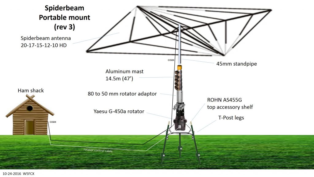
Here’s the original design of my Spiderbeam, mast and rotator system below.
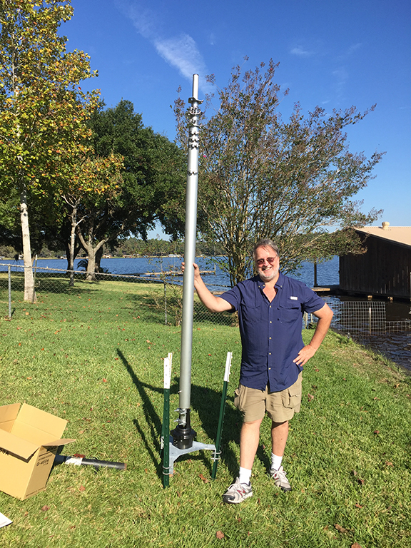
Here’s the actual setup. I’m standing next to the mast and rotor system where the antenna will go.
Here’s the assembled antenna shown below.
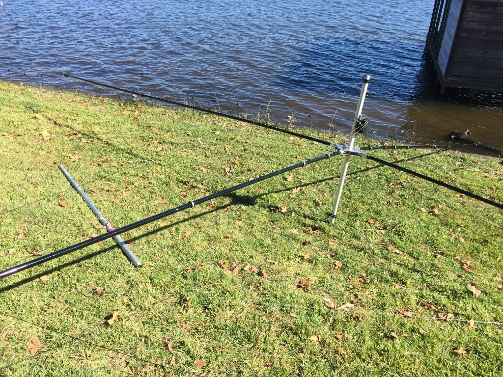
Spiderbeam ready to mount
Above we see the HD spiderbeam laying on the ground with its standpipe, along with the “mounting pole” laying on the ground to its left.
The mounting pole is used to raise the antenna up to the same height as retracted mast top, where it can be more easily transferred onto the mast. The mounting pole consists of two 1.25″ galvanized pipe sections – a 6′ section joined to a 2′ section with a barrel connector, creating an 8′ mounting pole.
Next, we place the antenna’s stand pipe onto the mounting pole.

You can tighten the stand pipe down around the top of the mounting pole.
Next pick up the antenna using the mounting pole and carry it over next to the mast. Set the mounting pole down on the ground next to the mast, as you see below.
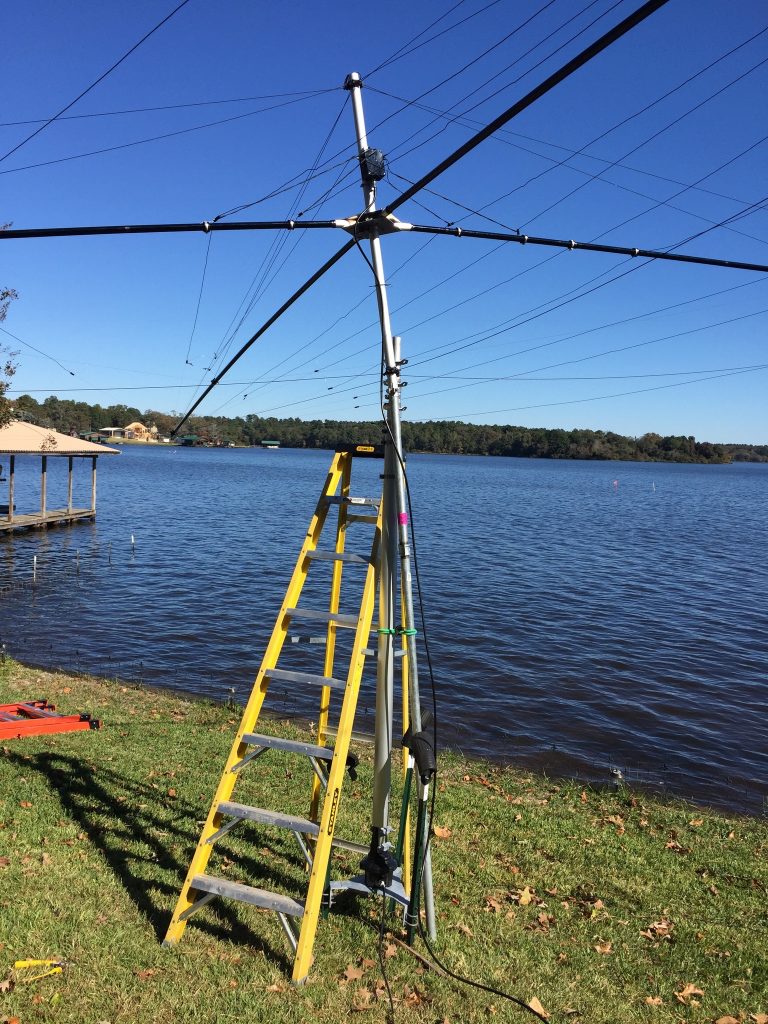
As shown above, the green bungee cord is used to secure the mounting pole to the mast. This keeps it secure during the transfer process that comes next.
Also, note the mast is sitting atop of my rotor – an inexpensive Yaesu G-450A rotator that turns the entire mast and antenna as one.
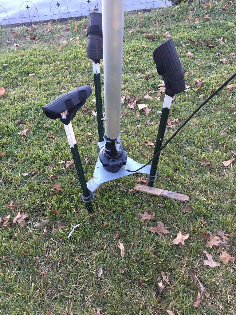
The rotator is mounted atop of a Rohn accessory plate, which is held up by three 5′ T-posts driven into the ground. I have placed rubber knee pads on the top of the T-posts to protect against accidental impalement, in the event one were to fall into one of those posts for any reason, as an additional precaution, during the project. The ladder is placed right up against the mast, so when I climb up on the ladder, I have the mast there as an extra support.
At this point, I climb onto the ladder, loosen the clamp on the antenna stand pipe, then hoist it off the mounting pole and onto the top of the mast, as shown below.
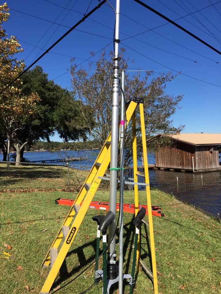
Now the antenna is now mounted on the top of the mast, ready for raising. By using the mounting pole, I have the extra lift, control and height needed to get the antenna and all its many wires and ropes well above the ladder and the mast, plus a way to hold it in place during the transfer operation. The HD spiderbeam and stand pipe weigh less than 30 pounds, but with its enormous wingspan of 33′ by 33′, it can be somewhat unwieldy to carry and control, especially by yourself. The mounting pipe solves all of these problems, making this part of the process easy enough for me to do by myself no problem.
Disconnect the mounting pole from the mast by releasing the bungee cord and remove the mounting pole for the next step. Be sure to fully tighten the stand pipe on the top of the mast, as we don’t want any potential for slippage of the antenna stand pipe at the mast junction.
Next we need to prepare the actuator pole. The actuator pole is used to automate raising the mast.
First, remove the top 2′ section of galvanized pipe from the mounting pole and set this pipe section aside. Next, we will place the linear actuator onto the 6′ pipe section, creating the actuator pole shown below. The linear actuator is mounted top the 6′ pipe section using a 1.25″ galvanized barrel connector (similar to the one used to connect the 2′ pipe section).
The actuator power wire runs down to the black control box, which has a DPDT momentary pushbutton switch, which provides either positive voltage (raise) or negative voltage (lower) to the actuator. Inside the box is a 120 VAC to 12 VDC converter – originally designed to convert 120 VAC to a 12 VDC cigarette lighter connection at 4.5 amps (the actuator only needs up to 2.5 amps). the converter cost about $6 at Amazon. I cut off the cigarette lighter connector and used split wiring to the DPDT momentary switch – easy enough.
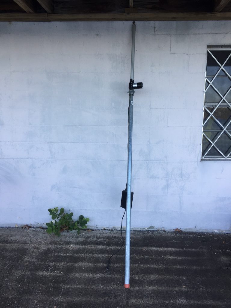
Now I can simply push the button on the controller box to raise or lower the actuator – very easy! The particular actuator I chose has up to 400 pounds of lifting power, more than enough for this job (a less expensive actuator would’ve done just fine – this one was available in 2 days via Amazon Prime, which is why I chose it – there were others available for around $75).
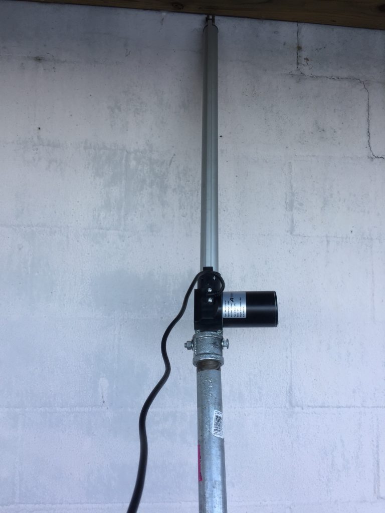
The closeup above shows how the actuator is mounted to the pipe. Using a drill press, a hole was drilled through the 1.25″ galvanized connector, then a carriage bolt is used to secure the bottom of the actuator to the pipe connector – very strong and safe for lifting purposes. Be sure you have a strong connection here.
Next, the actuator pole is placed next to the mast and secured using the same green bungee cord. Use whatever color you want – I had green available 🙂
I use a 3/16″ x 4′ PVC rubber coated chain to connect the actuator rod to the mast, as shown below. A 1/2″ x 3′ would probably be ideal, but once again, I ordered what was quickly available on Amazon Primte.
When the actuator rod extends upward, it causes the chain, which is wrapped around the mast, to bind up against the mast with enough friction to hold very tight, raising the mast. It’s a simple enough concept and it works perfectly.
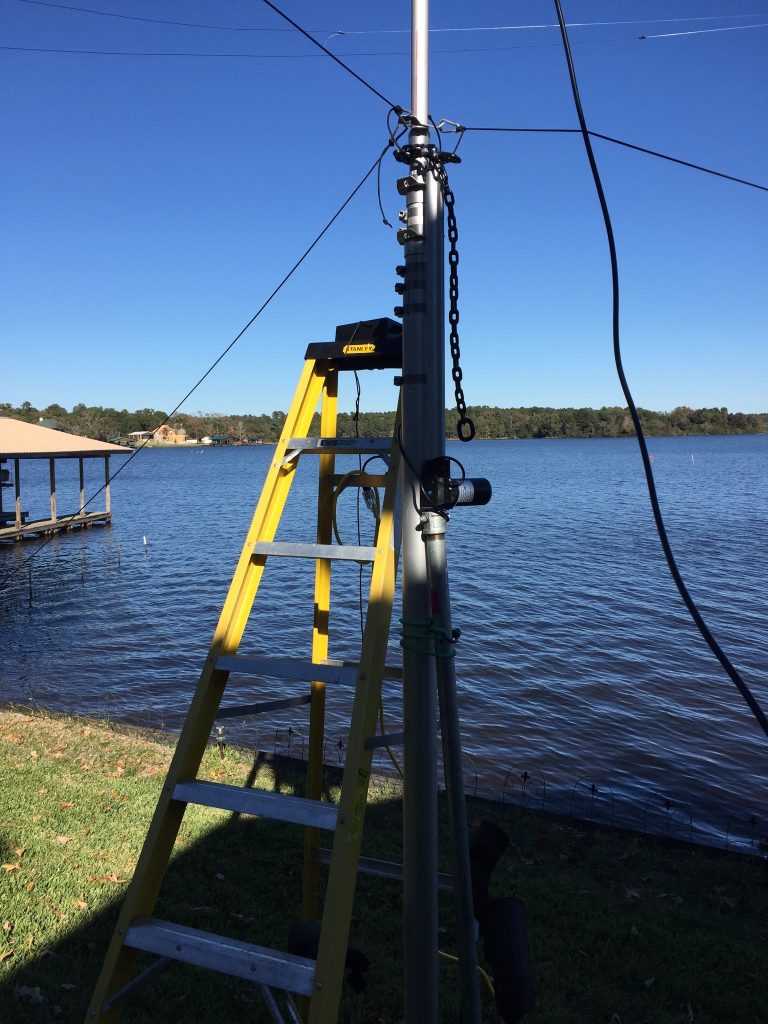
Below is a closeup shot of the chain to mast interface.
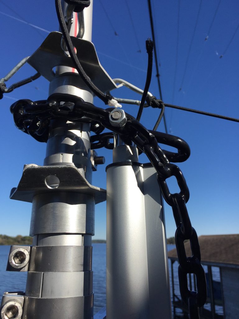
A carriage bolt is used to secure the chain to the actuator. I had to use my knife to cut out the rubber coating on the inside of the chain links for the bolt to slide through easier. This works surprisingly well.
When the actuator extends upward, the rubber-coated chain binds up against the mast, raising it up with the push of a button. I use this process to raise the mast.
IMPORTANT: Be certain the mast is dry and clean so the rubber-coated chain can grip it properly. Use a rag or paper towels to dry the mast if needed. If the mast is slippery (e.g., after being out in the weather for a while) the chain can slip, causing a section of the mast to come down unexpectedly. If that happens, it will cause your guy lines to all become loose, which will cause the mast to lean. This is a simple but very important precaution – ensure the mast is dry and clean before attaching the chain to it.
- Connect the chain around the mast section to be raised. I wrap the chain around the mast twice for better traction.
- Raise the actuator rod enough for the chain to begin to bind and take hold of the mast.
- Using the big allen wrench that came with the mast, loosen the mast clamp of the section to be raised
- Push the raise button on the actuator controller box to raise the mast section.
- Raise the mast 30″ (full extent of the actuator arm) or until the mast section markers show it’s raised to full height. Be careful not to push the mast section out of the tube or the entire mast and antenna will come crashing down around you!
- Using the allen wrench, tighten the mast section up.
- Push the lower button on the actuator controller to lower the chain. The chain will usually come down without binding – if needed, help it along if it attempts to bind up as it comes back down.
- Repeat steps 2 through 7 for each section of the mast. Make certain that you properly place the mast section clamps in the middle of the slotted area of the mast (see above) and fully tighten each section; otherwise, you’ll find your mast will slip when you try to rotate it.
- At appropriate intervals, manage your guy lines to provide sufficient looseness so the mast can be raised properly. Do not overpressure the mast with the actuator against tight guy lines. This is a bit tedious because you must go up and down the ladder to manage the guy lines, but is necessary to raise the mast safely, especially in high winds.
That’s it! After repeating the above procedure for each section of the mast, you will have your antenna hoisted fully up where it needs to be in about an hour (less if you have help with the guy lines). When the mast is up, you can disconnect the actuator pole by releasing the bungee cord.
Finally, I loosen the two U-bolts at the bottom of the mast where it connects to the rotator, then manually turn the mast and antenna to point the directors toward north at zero degrees (with the rotator already fully counter-clockwise to 0 degrees).
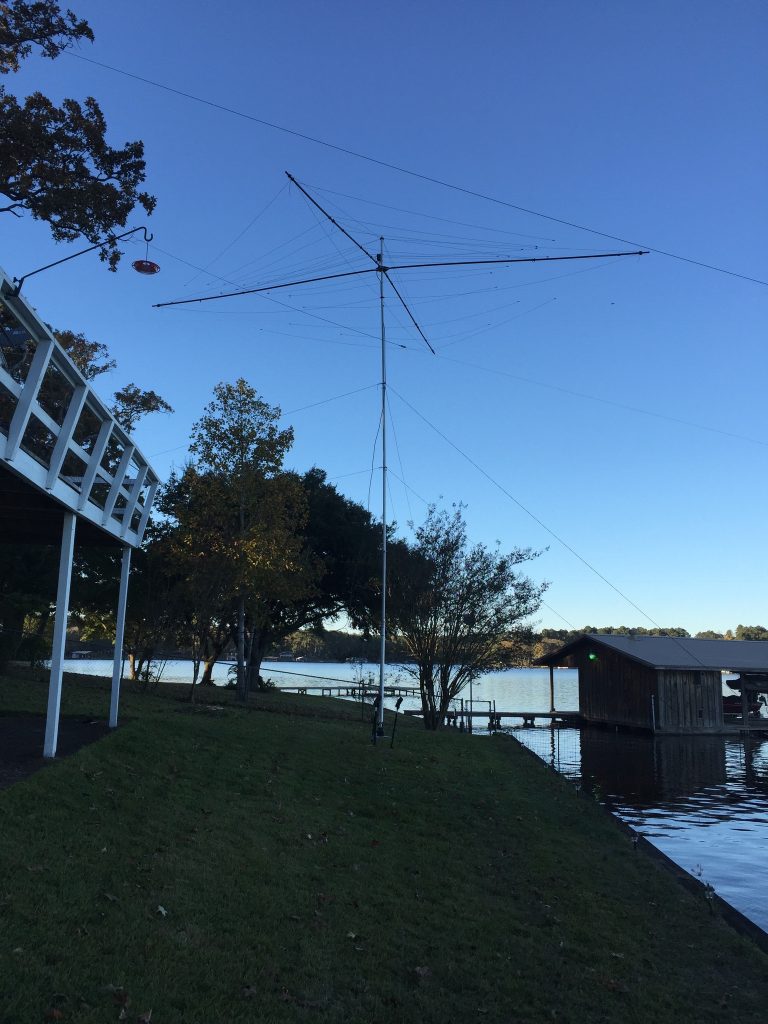
Spiderbeam 5-band HD
To see more about how this process of raising the antenna and mast works in a video, visit my earlier post or watch on my YouTube channel.
Have fun and enjoy operating your new beam antenna!! In a future post, I will provide a complete parts list for the project, for those who choose to take this on and want to raise and manage your Spiderbeam (or whatever type) antenna on a mast the easy way.
73’s,
Rick
W5FCX

Recent Comments